Do-it-yourself instructions
Below we provide a shopping list, build instructions, and the firmware to build your own usb-to-ttl device.
Shopping list
The items in this shopping list provide a good start to build a usb-to-ttl device without soldering and only basic assembly.
For convenience we provide the “price in euros” and the “item number” for all items, according to an online shop (we picked “Reichelt”).
To find the items, simply type in the “item number” on the Reichelt shop website.
name |
price in euros |
item-no (https://reichelt.com) |
|---|---|---|
arduino leonardo |
18.91 |
ARDUINO LEONARDO |
USB A to micro-B cable |
1.64 |
AK 676-AB2 |
10 pin spring-loaded terminal |
1.51 |
AST 021-10 |
8 pin spring-loaded terminal |
1.26 |
AST 021-08 |
25-pin D-SUB female connector |
0.61 |
D-SUB BU 25FB |
25 pole flat ribbon cable |
9.07 |
AWG 28-25F 3M |
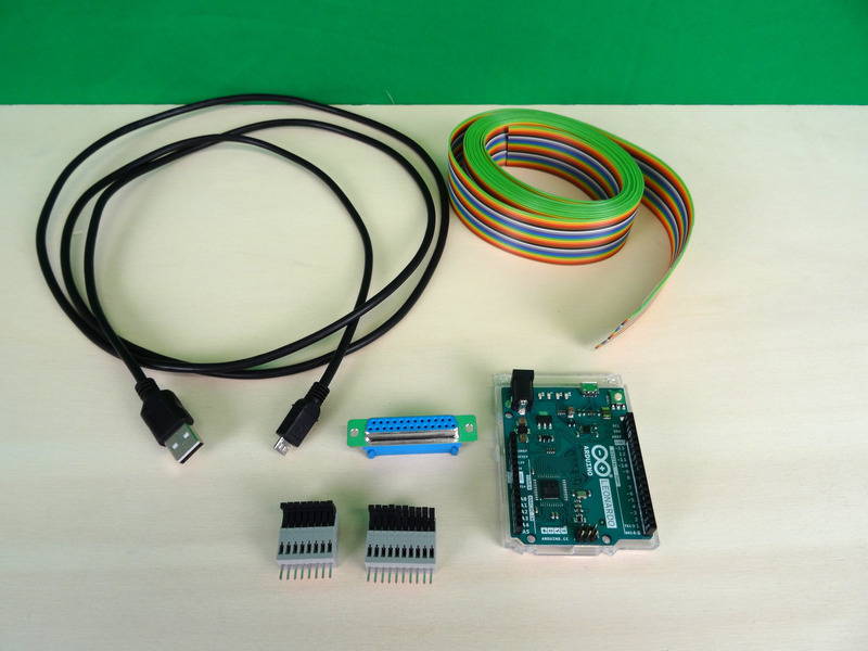
All items needed to assemble the usb-to-ttl device.
Build instructions
Step 1
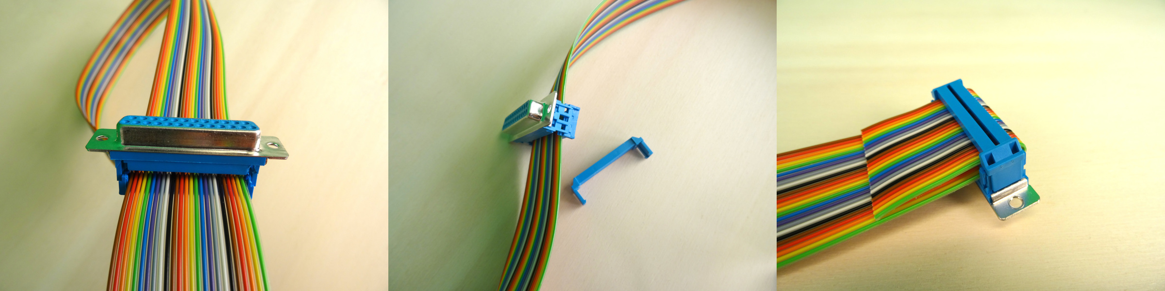
Attaching the db 25 connector to the cables.
Step 2
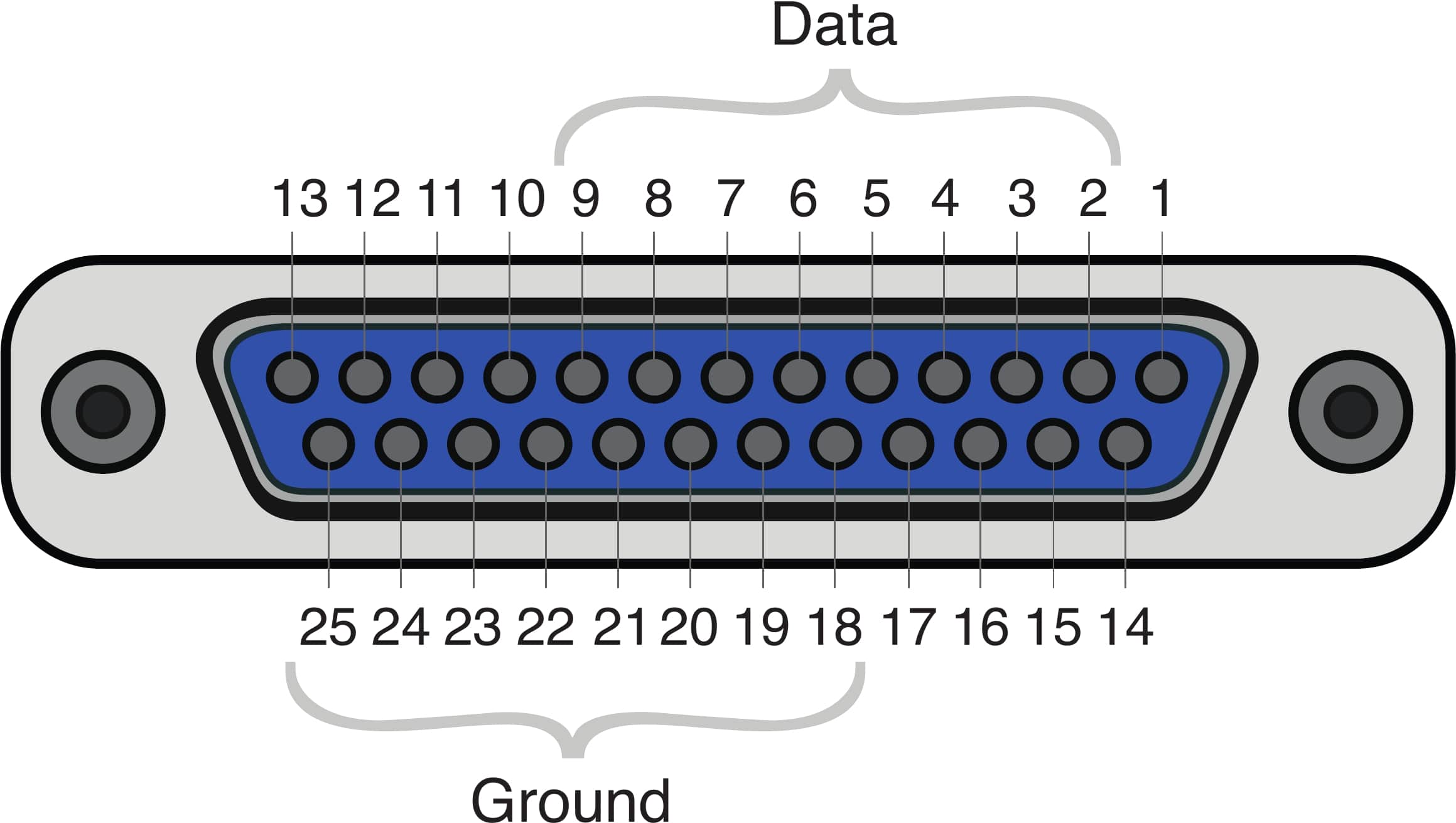
In the db 25 connector, pins 2-9 (8 pins in total) are for data. Pick any pin from 18-25 for the ground.
Step 3
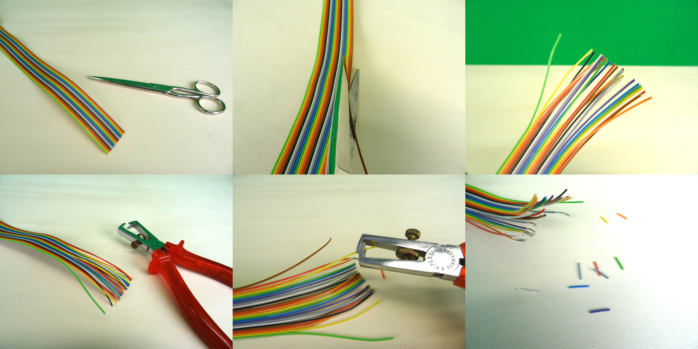
Preparing the wires for putting them into the spring-loaded terminals. Pick those leading to pins 2-9 for data, and one leading to any pin from 18-25 for the ground.
Step 4
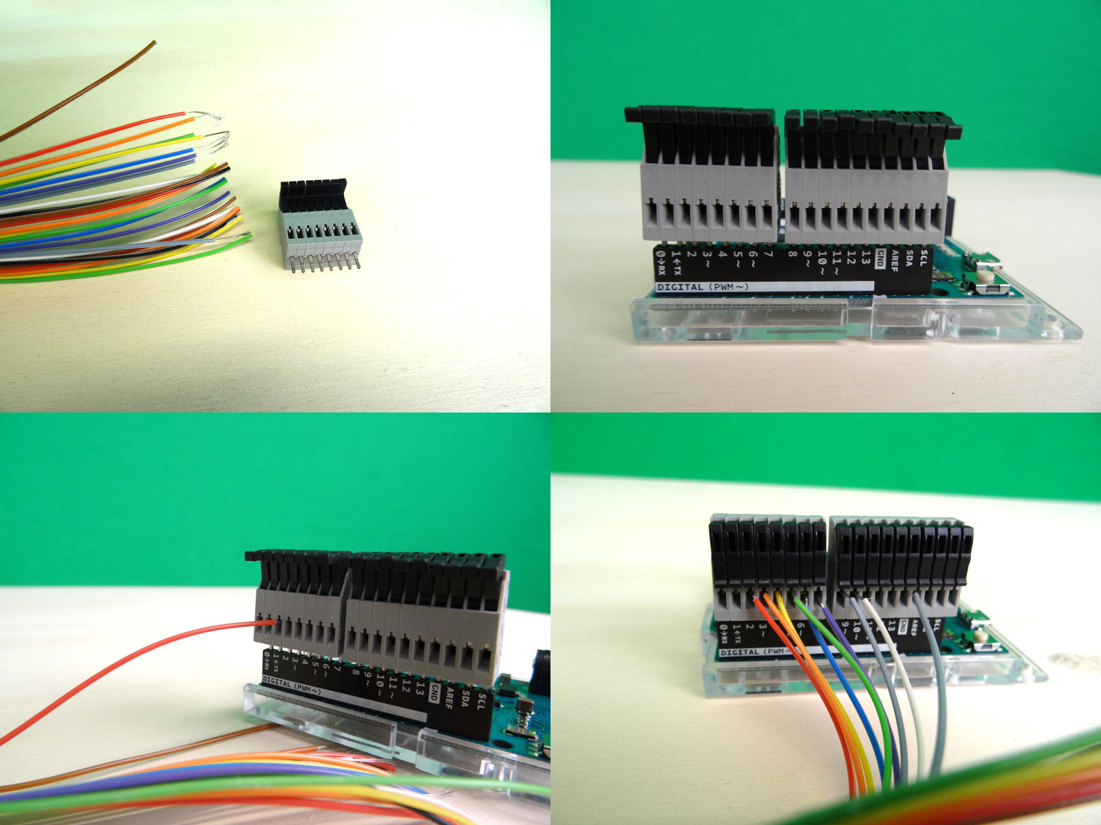
Connecting the wires with the spring-loaded terminals attached to the Arduino Leonardo. For simplicity, connect pins 2-9 from the db 25 connector to pins 2-9 on the Arduino. Connect the ground from the db 25 connector (any pin from 18-25) to the ground pin on the Arduino.
Step 5
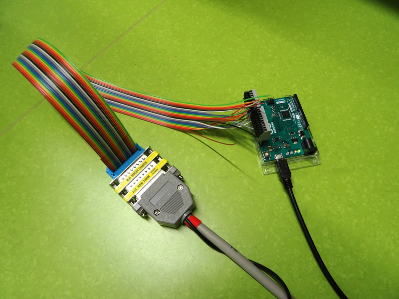
The finished device with an attached LPT cable (parallel port).
Firmware
This is the firmware that should be uploaded to the microcontroller. For uploading the firmware to the Arduino, please consult one of the abundant tutorials in the Arduino documentation.
Take care to define the outputPins according to how you connected your wires
(if you followed the instructions above, this will already be the case).
 1/*
 2Device firmware for a USB trigger box (Appelhoff & Stenner, 2021).
 3
 4MIT License
 5
 6Copyright 2021 Stefan Appelhoff, Tristan Stenner
 7
 8*/
 9
10#include "Arduino.h";
11// the following pin numbers depend on where you actually put the wires on your device
12const int outputPins[] = {2,3,4,5,6,7,8,9};
13
14void setup() {
15  Serial.begin(115200);
16  // "auto" is inferring variable type from "outputPins" array = int
17  for(auto pin: outputPins) pinMode(pin, OUTPUT);
18}
19
20// The expected byte is an ASCII character in the range of [0, 255]
21void loop() {
22  // If no new information, do nothing
23  if(!Serial.available()) return;
24  // Else, read a single byte and format it as ...
25  // type (_t) "unsigned (u) integer (int) of 8 (8) bits" = uint8_t
26  uint8_t inChar = Serial.read();
27
28  // Set the 8 pins to correspond to the byte
29  setOutputs(inChar);
30
31  // Leave the pins ON for long enough to be detected
32  // This depends on the sampling rate of the device that receives the byte
33  delay(2000);
34
35  // Then clear again and wait shortly
36  clearOutputs();
37  delay(8);
38}
39
40// Quick way of setting the 8 pins by using bitwise operators
41// for each pin check using "&", whether the byte corresponding to
42// own position is ON. We get the own position through the "<<" sliding
43// of a 1 across the 00000001 ... 00000010 ... 00000100 ... etc.
44// setting a pin to LOW if zero and else HIGH
45void setOutputs(uint8_t outChar) {
46  for(int i=0;i<8;i++) digitalWrite(outputPins[i], outChar&(1<<i));
47}
48
49
50// Clearing all pins, setting their output to LOW
51void clearOutputs() {
52  for(auto pin: outputPins) digitalWrite(pin, LOW);
53}